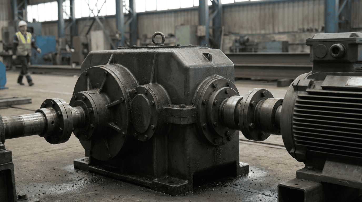
Preventing electrical fluting and bearing damage in gearboxes is essential for plants using variable frequency drives, electric motors, servo systems, generators, and other electrically coupled rotating equipment. When stray shaft voltage discharges through gearbox bearings, it can create microscopic electrical discharge machining marks that eventually form washboard-like fluting, noise, vibration, lubricant degradation, and premature bearing failure. For maintenance managers, plant engineers, reliability teams, mechanics, and purchasing professionals, the goal is not only to replace damaged bearings but to eliminate the electrical path that caused the failure. This guide explains the causes, symptoms, inspection methods, troubleshooting steps, prevention strategies, and repair-versus-replacement decisions that protect gearbox reliability.
Electrical fluting in gearbox bearings is caused by stray electrical current passing through bearing rolling elements and races, often from VFD-driven motors, poor grounding, capacitive coupling, or inadequate shaft grounding. The best prevention strategy is to create a low-resistance path away from the gearbox bearings using shaft grounding rings, insulated bearings, ceramic hybrid bearings, proper motor and gearbox grounding, shielded VFD cable, correct bonding practices, and routine vibration and lubricant analysis. If fluting is already present, inspect bearings, lubricant, grounding, motor-to-gearbox alignment, and drive wiring before deciding whether to repair or replace the gearbox.
In the realm of industrial machinery, understanding the implications of electrical fluting and bearing damage in gearboxes is crucial for maintaining operational efficiency. For those interested in exploring effective repair solutions for such issues, a related article can be found at Industrial Gearbox Repair in Montana, which provides insights into the repair processes and preventative measures that can be taken to mitigate these common problems.
What Is Electrical Fluting in Gearbox Bearings?
Electrical fluting is a bearing failure pattern caused by electrical discharge across the thin lubricant film separating bearing rolling elements from raceways. The discharge creates tiny craters, often called electrical discharge machining or EDM damage. Over time, repeated current passage creates evenly spaced grooves across the bearing race. These grooves resemble a washboard pattern and are commonly called fluting.
In gearboxes, electrical fluting can occur in:
- Input shaft bearings connected to VFD-driven motors
- Output shaft bearings connected to driven equipment
- Intermediate shaft bearings in multi-stage gear reducers
- Motor bearings and gearbox bearings in coupled drive systems
- Bearings in servo gearboxes, wind turbine gearboxes, conveyors, mixers, extruders, pumps, and cooling tower drives
Electrical bearing damage is especially concerning because it may be misdiagnosed as lubrication failure, overload, contamination, misalignment, or normal fatigue. While those conditions can also damage bearings, electrical fluting has distinctive visual and vibration characteristics that require specific corrective action.
How Electrical Discharge Damages Bearings
Bearings rely on a microscopic lubricant film to separate metal surfaces. When shaft voltage builds high enough to overcome the dielectric strength of that lubricant film, it arcs from the shaft through the rolling element to the raceway. Each arc creates a small pit or crater.
As the bearing continues operating, rolling elements pass over these pits repeatedly. The damaged surface evolves into:
- Frosted or matte raceway appearance
- Micro-pitting
- Fluting grooves
- Increased vibration
- Audible whining or growling
- Elevated operating temperature
- Lubricant oxidation and darkening
- Premature bearing failure
According to bearing manufacturers such as SKF and Timken, electrical erosion is a recognized bearing failure mode in rotating machinery, particularly where variable frequency drives are used.
External references:
- SKF bearing damage and failure analysis: https://www.skf.com
- Timken bearing damage analysis: https://www.timken.com
- AGMA gearbox standards and technical resources: https://www.agma.org
- Noria lubrication and oil analysis resources: https://www.noria.com
Common Causes of Electrical Fluting and Bearing Damage
Electrical fluting is usually not caused by one isolated issue. It often results from a combination of electrical design, grounding, installation, lubrication, and operating factors.
Variable Frequency Drives and Common-Mode Voltage
Variable frequency drives are one of the most common contributors to electrical bearing damage. VFDs switch voltage rapidly to control motor speed. This switching can create common-mode voltage, which may induce shaft voltage in the motor rotor and connected drivetrain.
If the voltage seeks a path to ground through the motor bearings, gearbox bearings, or driven equipment bearings, electrical discharge can occur.
Common VFD-related contributors include:
- High switching frequency
- Long motor cable runs
- Improper cable shielding
- Poor grounding practices
- Lack of shaft grounding
- No insulated bearing protection
- Improper VFD output filtering
- Motor and gearbox mounted on poorly bonded structures
Poor Grounding and Bonding
Grounding and bonding are critical in preventing stray current from passing through bearings. A motor may be grounded, but if the gearbox, baseplate, skid, or driven machine is not properly bonded, current may use the bearings as part of the return path.
Potential grounding and bonding problems include:
- Painted mounting surfaces interrupting electrical continuity
- Loose or corroded ground connections
- Missing bonding straps between motor and gearbox
- High-resistance grounding paths
- Multiple ground points causing circulating currents
- Poorly grounded VFD cabinets
- Improperly terminated cable shields
Capacitive Coupling Between Motor and Gearbox
Even without a direct electrical fault, voltage can transfer capacitively from motor windings to the rotor and shaft. In a coupled motor-gearbox arrangement, this voltage can travel into the gearbox input shaft. If no safe discharge path exists, current may discharge through gearbox bearings.
This is common in:
- Helical gear reducers
- Right-angle gearboxes
- Parallel shaft gearboxes
- Planetary gearboxes
- Servo gearboxes
- Cooling tower gearboxes
- Conveyor gear drives
- Pump and compressor gear drives
Inadequate Bearing Protection
Some applications require special bearing protection. Standard steel bearings are conductive and can allow current to pass through rolling elements and raceways. If the design lacks shaft grounding, insulated bearings, or hybrid ceramic bearings, gearbox bearings may be vulnerable.
Protective technologies include:
- Shaft grounding rings
- Conductive shaft brushes
- Insulated bearing housings
- Insulated bearings
- Ceramic hybrid bearings
- Grounding straps
- VFD output reactors or filters
- Properly shielded cables
Lubrication Conditions That Increase Risk
Lubricant does not cause stray current, but lubricant condition influences how electrical discharge behaves. The lubricant film acts as an insulator until voltage exceeds its dielectric strength. Degraded or contaminated oil may change electrical resistance and worsen surface damage after discharge occurs.
Lubrication-related contributors include:
- Oxidized oil
- Water contamination
- Particulate contamination
- Incorrect viscosity
- Additive depletion
- Overheating
- Foaming or aeration
- Inadequate oil film thickness
For more on lubricant-related gearbox failures, see Industrial Gearbox Solutions’ maintenance resources: https://industrialgearboxsolutions.com/gearbox-maintenance/
Industrial gearbox bearing failure can lead to costly downtime and production losses, so it’s important to address the issue promptly. Industrial gearbox bearing failure
Symptoms of Electrical Bearing Damage in Gearboxes
Electrical fluting often progresses from subtle symptoms to severe mechanical failure. Early detection can prevent catastrophic downtime.
Audible Noise
A fluted bearing often produces a distinctive whining, humming, or growling sound. In later stages, the sound may resemble mechanical roughness or gear mesh noise.
Common audible symptoms include:
- High-pitched whine
- Rhythmic rumble
- Growling at certain speeds
- Increased noise after VFD installation
- Noise that changes with motor speed
Vibration Changes
Vibration analysis is one of the best methods for detecting bearing damage. Electrical fluting can produce bearing defect frequencies and high-frequency vibration signatures.
Look for:
- Increasing high-frequency vibration
- Bearing outer race defect frequency
- Bearing inner race defect frequency
- Broadband vibration increases
- Peaks associated with bearing geometry
- Changes after VFD speed adjustments
- Sidebands around running speed or bearing frequencies
Lubricant Contamination and Darkening
Electrical discharge can create localized heat and metal particles. Bearing degradation can contaminate the oil or grease.
Oil analysis may show:
- Elevated iron
- Increased particle count
- Darkened oil
- Oxidation
- Varnish potential
- Water contamination
- Additive depletion
- Wear debris consistent with bearing damage
Noria offers helpful guidance on oil analysis, contamination control, and lubricant condition monitoring: https://www.noria.com
Temperature Increase
Damaged bearing surfaces increase friction. As fluting progresses, bearing temperature may rise. However, temperature alone is not enough to confirm electrical damage because many gearbox faults generate heat.
Temperature symptoms include:
- Hotter bearing housing
- Higher oil sump temperature
- Temperature rise after VFD retrofit
- Localized heat near input shaft bearings
- Thermal instability under load
Premature Bearing Failure
If gearbox bearings fail much earlier than expected, electrical damage should be considered, especially when failures occur repeatedly after bearing replacement.
Warning signs include:
- Repeated input shaft bearing failures
- Similar bearing failures across multiple identical drives
- Failures after motor/VFD upgrades
- Bearings showing frosted raceways or fluting
- No clear evidence of overload, misalignment, or lubrication starvation
Understanding the intricacies of electrical fluting and bearing damage in industrial gearboxes is crucial for maintaining operational efficiency. For those interested in exploring alternatives to traditional gearboxes, a related article provides valuable insights into various options available in the market. You can read more about these alternatives in the article on Sew Eurodrive Gearbox Alternatives, which discusses how different designs can help mitigate issues related to electrical fluting and enhance overall gearbox performance.
Electrical Fluting vs. Other Gearbox Bearing Failures
| Types of Damage | Causes | Effects |
|---|---|---|
| Electrical Fluting | High-frequency electrical currents, improper grounding | Noise, vibration, premature bearing failure |
| Bearing Damage | Overloading, misalignment, contamination | Increased friction, heat generation, reduced lifespan |
Electrical fluting can be confused with other bearing damage modes. Correct identification matters because replacing the bearing without correcting the electrical source will lead to repeat failure.
| Failure Mode | Typical Appearance | Common Cause | Key Difference |
|||||
| Electrical fluting | Washboard grooves, frosted raceways, EDM pits | Shaft voltage and stray current | Often linked to VFDs or grounding issues |
| Lubrication starvation | Smearing, discoloration, heat damage | Low oil, wrong viscosity, blocked lubrication | Usually shows heat and metal-to-metal contact |
| Contamination damage | Dents, scratches, abrasive wear | Dirt, water, debris | Random surface damage rather than uniform fluting |
| Overload fatigue | Spalling, cracking | Excessive load or shock load | Fatigue pattern often load-zone related |
| Misalignment | Uneven wear pattern | Coupling or shaft misalignment | Wear pattern is directional or localized |
| False brinelling | Fretting marks at roller spacing | Vibration while stationary | Usually occurs during transport or standby |
Inspection Clues That Suggest Electrical Damage
Electrical damage may be present when you find:
- Frosted gray raceways
- Fine axial grooves
- Uniform fluting across raceway
- Micro-craters under magnification
- Darkened lubricant
- Damage on multiple bearings in an electrical path
- Repeat failure after bearing replacement
- Recent VFD installation or motor upgrade
Troubleshooting Electrical Bearing Damage in Gearboxes
A structured troubleshooting process prevents wasted time and unnecessary component replacement.
Step 1: Document the Failure History
Start with a complete operating and maintenance history.
Record:
- Gearbox model and serial number
- Motor horsepower and speed
- VFD make, model, and settings
- Date of VFD installation or retrofit
- Bearing replacement history
- Lubricant type and change interval
- Load profile and duty cycle
- Vibration trend history
- Oil analysis reports
- Alignment records
- Grounding modifications
For gearbox inspections and repair evaluations, Industrial Gearbox Solutions can support failure analysis and rebuild planning: https://industrialgearboxsolutions.com/gearbox-repair/
Step 2: Inspect the Bearing
If the gearbox is opened, preserve the bearing and document the condition before cleaning it aggressively.
Inspection best practices:
- Photograph raceways, rollers, cages, and lubricant
- Look for fluting under bright light
- Use magnification to identify EDM craters
- Compare inner and outer race damage
- Check for spalling, smearing, heat discoloration, and corrosion
- Save lubricant samples
- Label bearing orientation and location
Step 3: Measure Shaft Voltage
Shaft voltage testing helps determine whether electrical discharge risk exists. This testing is often performed using an oscilloscope, shaft voltage probe, or specialized shaft voltage detection equipment.
Measure:
- Motor shaft voltage
- Gearbox input shaft voltage
- Voltage across coupling
- Voltage between gearbox housing and ground
- Voltage under different VFD speeds
- Voltage during acceleration and deceleration
- Voltage at normal load
Because VFD waveforms can be complex, use personnel qualified in electrical testing and safety procedures.
Step 4: Check Grounding and Bonding
A visual inspection is not enough. Use electrical resistance testing to verify low-resistance bonding.
Check:
- Motor frame to ground
- Gearbox housing to ground
- Baseplate to ground
- VFD cabinet to ground
- Cable shield termination
- Coupling guard and auxiliary components
- Ground straps across flexible mounts
- Paint, corrosion, or gasket barriers
Step 5: Review VFD Installation
The drive installation may need correction.
Review:
- Cable type
- Cable length
- Shield grounding
- Carrier frequency
- Output reactor or filter use
- Motor insulation rating
- Grounding layout
- Motor manufacturer recommendations
- VFD manufacturer recommendations
Step 6: Rule Out Mechanical Contributors
Electrical fluting may coexist with mechanical problems. Confirm that the gearbox is not also affected by:
- Misalignment
- Soft foot
- Excessive belt tension
- Overload
- Improper bearing preload
- Lubricant starvation
- Contamination
- Gear mesh problems
- Foundation looseness
For additional gearbox failure analysis guidance, see: https://industrialgearboxsolutions.com/gearbox-inspection/
Inspection Methods for Early Detection
Early detection reduces downtime and helps maintenance teams plan repairs instead of reacting to emergency failures.
Vibration Analysis
Vibration analysis can identify bearing distress before total failure. Trending is more valuable than one-time readings.
Recommended vibration practices:
- Establish baseline readings after installation
- Monitor overall vibration and high-frequency energy
- Track bearing defect frequencies
- Compare identical gearboxes across the plant
- Review trends after VFD parameter changes
- Investigate sudden increases immediately
Oil Analysis
Oil analysis is particularly useful for splash-lubricated and circulating-oil gearboxes.
Key oil analysis tests:
| Test | What It Reveals | Why It Matters |
||||
| Particle count | Cleanliness level | Contamination accelerates bearing wear |
| Spectrometric analysis | Wear metals | Elevated iron may indicate bearing or gear wear |
| Ferrous density | Larger ferrous debris | Useful for active wear detection |
| Water content | Moisture contamination | Water reduces lubricant performance |
| Viscosity | Oil film strength | Incorrect viscosity increases contact stress |
| Oxidation | Oil degradation | Degraded oil can increase varnish and wear |
| Acid number | Chemical degradation | Indicates oil aging or contamination |
Borescope Inspection
A borescope can help inspect accessible bearing areas and internal gearbox components without full disassembly. While it may not reveal all bearing race damage, it can identify:
- Discoloration
- Debris
- Oil condition
- Gear tooth damage
- Bearing cage damage
- Corrosion
- Evidence of overheating
Thermography
Infrared thermography can identify abnormal heating at bearing housings, motor bearings, couplings, and electrical cabinets.
Use thermography to compare:
- Similar drives under similar load
- Motor drive-end and non-drive-end bearings
- Gearbox input and output bearing areas
- VFD cabinet connections
- Grounding connections
- Coupling area temperature
Visual Bearing Failure Analysis
When a bearing is removed, visual inspection is essential. Consult bearing damage references from SKF and Timken to compare failure modes and avoid misdiagnosis.
Look for:
- Fluting pattern
- EDM pitting
- Frosting
- Spalling
- Smearing
- Cage wear
- Corrosion
- Lubrication staining
- Heat discoloration
Prevention Strategies for Electrical Fluting
Preventing electrical fluting requires controlling shaft voltage, providing safe discharge paths, and maintaining gearbox mechanical health.
Install Shaft Grounding Rings
Shaft grounding rings provide a low-impedance path for shaft current to discharge safely to ground instead of through bearings. They are commonly installed on motors and may also be installed near gearbox input shafts depending on system design.
Benefits include:
- Reduces shaft voltage
- Protects motor and gearbox bearings
- Useful for VFD-driven systems
- Can be retrofitted in many applications
- Supports long-term bearing reliability
Installation considerations:
- Shaft surface must be clean and conductive
- Ring must be properly bonded to ground
- Avoid paint or corrosion at mounting points
- Follow manufacturer instructions
- Inspect periodically for contamination or wear
Use Insulated Bearings or Hybrid Ceramic Bearings
Insulated bearings interrupt current flow through the bearing. Hybrid ceramic bearings use ceramic rolling elements that are electrically insulating and resistant to electrical erosion.
| Bearing Protection Option | Advantage | Limitation |
||||
| Insulated bearing | Blocks current path through bearing | Current may seek another bearing path |
| Hybrid ceramic bearing | High electrical resistance and wear resistance | Higher upfront cost |
| Shaft grounding ring | Diverts current away from bearing | Must be correctly installed and maintained |
| Insulated housing | Helps isolate bearing path | Requires careful system design |
| Output filter/reactor | Reduces VFD-related voltage stress | Adds cost and cabinet space |
In many critical applications, a combined approach is best: shaft grounding plus insulated or hybrid bearings.
Improve Grounding and Bonding
Proper grounding and bonding reduce the chance that gearbox bearings become part of an electrical path.
Best practices:
- Bond motor frame to gearbox housing
- Bond gearbox housing to baseplate
- Bond skid or frame to plant ground
- Remove paint at bonding points
- Use corrosion-resistant connections
- Install flexible bonding straps across rubber mounts
- Verify low resistance after installation
- Inspect grounding during preventive maintenance
Use Proper VFD Cable and Shielding
VFD cable should be selected and installed according to drive and motor manufacturer recommendations. Improper cable can worsen common-mode voltage and electromagnetic interference.
Recommended practices:
- Use shielded VFD-rated cable
- Terminate shields correctly
- Keep cable runs as short as practical
- Avoid running VFD cables parallel to sensitive instrumentation
- Use symmetrical grounding conductors where appropriate
- Follow electrical codes and OEM instructions
Consider VFD Output Filters or Reactors
Output reactors, dV/dt filters, and sine wave filters can reduce voltage stress and electrical noise in motor-drive systems.
They may be helpful when:
- Motor leads are long
- Motors are older or not inverter-duty
- Shaft voltage is high
- Multiple bearing failures have occurred
- Electrical noise affects instrumentation
- The application is critical to production
Maintain Lubricant Health
Lubrication cannot replace electrical protection, but healthy lubricant reduces secondary damage and supports bearing life.
Lubrication best practices:
- Use OEM-recommended lubricant viscosity and type
- Maintain correct oil level
- Filter oil to target cleanliness levels
- Control water contamination
- Monitor oil temperature
- Avoid mixing incompatible lubricants
- Conduct regular oil analysis
- Replace oil based on condition, not guesswork
For gearbox lubrication support, visit: https://industrialgearboxsolutions.com/gearbox-lubrication/
Repair vs. Replacement: What Should You Do?
When electrical fluting is discovered, the right decision depends on damage severity, gearbox criticality, lead time, cost, and root cause.
When Repair May Be Appropriate
Repair or rebuild is often appropriate when:
- Gear housing is in good condition
- Gear teeth are reusable or repairable
- Shafts are within tolerance
- Bearing fits are not damaged
- Replacement gearbox lead time is long
- Upgraded bearings and grounding can be installed
- The gearbox is large, custom, or expensive
- Failure analysis confirms correctable root cause
A proper repair should include:
- Bearing replacement
- Seal replacement
- Shaft and housing inspection
- Gear inspection
- Cleaning and flushing
- Alignment checks
- Lubrication system inspection
- Electrical mitigation upgrades
- Test run when practical
When Replacement May Be Better
Replacement may be the better choice when:
- Housing bores are damaged
- Shafts are severely worn
- Gear teeth have major pitting or cracking
- Repair cost approaches replacement cost
- The gearbox is obsolete but replaceable with a standard unit
- Production cannot tolerate uncertain repair life
- Multiple internal components are damaged
- A redesigned gearbox offers improved reliability
Decision Matrix
| Factor | Repair Favored | Replacement Favored |
||||
| Gearbox size | Large or custom | Small standard unit |
| Lead time | Replacement unavailable | New unit readily available |
| Damage level | Bearings/seals only | Housing, gears, shafts damaged |
| Cost | Repair much lower | Repair near replacement cost |
| Criticality | Rebuild with upgrades possible | Need guaranteed new asset |
| Root cause | Correctable | Design unsuitable for application |
Before repairing or replacing, correct the electrical cause. Otherwise, the new or rebuilt gearbox may suffer the same failure.
Maintenance Best Practices for Long-Term Gearbox Reliability
A strong maintenance program combines mechanical inspection, electrical testing, lubrication control, and documentation.
Preventive Maintenance Checklist
| Task | Frequency | Responsible Team |
||:||
| Check gearbox oil level | Weekly/monthly | Maintenance |
| Inspect grounding straps | Quarterly | Electrical/maintenance |
| Vibration data collection | Monthly/quarterly | Reliability |
| Oil sampling | Quarterly/semiannual | Reliability/lubrication |
| Thermography | Semiannual | Electrical/reliability |
| Coupling alignment check | During outages | Maintenance |
| Shaft voltage testing | After VFD changes or annually | Electrical/reliability |
| Inspect shaft grounding rings | Quarterly/semiannual | Maintenance |
| Review VFD parameters | After changes or annually | Electrical engineering |
| Borescope inspection | Annual/outage | Reliability/maintenance |
Installation Best Practices
During installation or commissioning:
- Verify gearbox and motor alignment
- Confirm proper soft foot correction
- Use correct coupling spacing
- Check foundation rigidity
- Install bonding straps before startup
- Confirm lubrication type and level
- Baseline vibration and temperature
- Measure shaft voltage on VFD systems
- Document VFD settings
- Confirm cable shield termination
- Record bearing protection devices installed
Purchasing Considerations
Purchasing professionals can help prevent repeat failures by specifying reliability requirements upfront.
Include in purchase specifications:
- Inverter-duty motor compatibility
- Shaft grounding provisions
- Insulated or hybrid ceramic bearings when needed
- Grounding and bonding requirements
- VFD cable recommendations
- Lubrication requirements
- Oil sampling ports
- Condition monitoring provisions
- Documentation package
- Failure analysis support
- Warranty terms related to VFD operation
Recommended Branded Images
Use original, branded visuals that help readers identify symptoms and prevention methods.
| Image Concept | Suggested Alt Text | Caption |
||||
| Close-up of fluted bearing race | Electrical fluting damage on gearbox bearing raceway | Fluting creates a washboard pattern that indicates electrical discharge through the bearing. |
| Technician measuring shaft voltage | Reliability technician testing shaft voltage on gearbox input shaft | Shaft voltage testing helps confirm whether gearbox bearings are exposed to stray current. |
| Shaft grounding ring on motor | Shaft grounding ring installed on VFD-driven motor | Shaft grounding rings provide a safe discharge path away from bearings. |
| Gearbox grounding strap | Bonding strap connecting motor and gearbox housing | Proper bonding helps prevent current from passing through gearbox bearings. |
| Oil sample from damaged gearbox | Dark gearbox oil sample with bearing wear debris | Oil analysis can reveal bearing wear, contamination, and lubricant degradation. |
| VFD and shielded cable installation | VFD cabinet with properly shielded motor cable | Correct VFD wiring reduces electrical stress on rotating equipment. |
Authoritative Standards and Resources
Use respected references when developing plant standards and failure analysis procedures:
- SKF bearing failure analysis resources: https://www.skf.com
- Timken bearing damage analysis resources: https://www.timken.com
- AGMA technical standards for gear drives: https://www.agma.org
- Noria lubrication and oil analysis education: https://www.noria.com
- IEEE resources for motor grounding and VFD-related electrical issues: https://www.ieee.org
Frequently Asked Questions
What causes electrical fluting in gearbox bearings?
Electrical fluting is caused by stray current discharging through gearbox bearings. This often happens in VFD-driven motor systems where shaft voltage builds up and seeks a path to ground through the motor, coupling, gearbox shaft, bearings, and housing.
How can I tell if bearing damage is electrical fluting?
Look for frosted raceways, tiny EDM pits, and evenly spaced washboard-like grooves across the bearing race. Vibration analysis may show bearing defect frequencies, and failures often repeat after bearing replacement unless grounding or shaft voltage issues are corrected.
Can a VFD damage gearbox bearings?
Yes. A VFD can contribute to gearbox bearing damage by generating common-mode voltage and shaft voltage. The risk is higher when grounding, bonding, cable shielding, or bearing protection is inadequate.
Will replacing the bearing solve the problem?
Not by itself. Replacing the bearing removes the damaged component, but it does not eliminate the electrical source. You must also address shaft grounding, insulated bearings, VFD wiring, bonding, and lubrication condition.
Are ceramic bearings worth the cost?
Hybrid ceramic bearings can be worth the cost in critical applications because ceramic rolling elements provide electrical insulation and resistance to electrical erosion. However, they should be selected as part of a system-level solution, not as a standalone fix.
Where should shaft grounding be installed?
Shaft grounding is commonly installed on the motor shaft, especially in VFD-driven applications. In some systems, additional grounding near the gearbox input shaft may be recommended. The correct location depends on the drivetrain layout and current path.
Can oil analysis detect electrical fluting?
Oil analysis can detect wear debris, oxidation, contamination, and lubricant degradation caused by bearing damage. However, it cannot always confirm electrical fluting by itself. Combine oil analysis with vibration data, bearing inspection, and shaft voltage testing.
What departments should be involved in solving electrical bearing damage?
The best results come from collaboration between maintenance, reliability, electrical engineering, mechanical engineering, lubrication specialists, and purchasing. Electrical fluting is both an electrical and mechanical reliability issue.
Key Takeaways
- Electrical fluting occurs when stray current discharges through gearbox bearings.
- VFD-driven motors are a common source of shaft voltage and bearing current.
- Symptoms include bearing noise, high-frequency vibration, darkened lubricant, elevated temperature, and premature bearing failure.
- Fluted bearings often show frosted raceways, EDM pits, and washboard grooves.
- Replacing bearings without correcting the electrical path leads to repeat failures.
- Prevention may include shaft grounding rings, insulated bearings, hybrid ceramic bearings, proper bonding, shielded VFD cable, and output filters.
- Vibration analysis, oil analysis, thermography, borescope inspection, and shaft voltage testing improve early detection.
- Repair-versus-replacement decisions should consider damage severity, gearbox criticality, cost, lead time, and root cause.
- Purchasing specifications should include electrical protection requirements for VFD-driven gearbox applications.
SEO Metadata
SEO Title
Preventing Electrical Fluting and Bearing Damage in Gearboxes
Meta Description
Learn how to prevent electrical fluting and bearing damage in gearboxes with shaft grounding, insulated bearings, VFD best practices, inspection methods, troubleshooting, and repair guidance.
Primary Keyword
Preventing electrical fluting and bearing damage in gearboxes
Secondary Keywords
- electrical fluting in gearbox bearings
- gearbox bearing damage
- shaft voltage gearbox
- VFD bearing damage
- electrical discharge bearing failure
- gearbox bearing fluting
- shaft grounding ring gearbox
- insulated bearings for gearboxes
- hybrid ceramic bearings gearbox
- gearbox failure analysis
Suggested URL Slug
preventing-electrical-fluting-bearing-damage-gearboxes
Search Intent
Informational and commercial investigation for maintenance, reliability, engineering, and purchasing teams seeking to diagnose, prevent, repair, or specify protection against gearbox bearing electrical damage.
Suggested Internal Links
- Gearbox Repair: https://industrialgearboxsolutions.com/gearbox-repair/
- Gearbox Inspection: https://industrialgearboxsolutions.com/gearbox-inspection/
- Gearbox Maintenance: https://industrialgearboxsolutions.com/gearbox-maintenance/
- Gearbox Lubrication: https://industrialgearboxsolutions.com/gearbox-lubrication/
- Industrial Gearbox Rebuilds: https://industrialgearboxsolutions.com/gearbox-rebuild/
Conclusion
Electrical fluting is a preventable cause of gearbox bearing failure, but it requires more than simply replacing damaged bearings. The most reliable solution is a system-level approach that combines electrical mitigation, mechanical inspection, lubrication control, and condition monitoring. For VFD-driven equipment, plants should verify grounding and bonding, measure shaft voltage, inspect bearings for EDM damage, maintain lubricant health, and use shaft grounding or insulated bearing technologies where appropriate. By identifying the true current path and correcting it before the next startup, maintenance and reliability teams can extend gearbox life, reduce unplanned downtime, and protect critical production assets.
If your gearbox is showing signs of electrical fluting, bearing noise, vibration, or repeat failure, request an inspection or repair evaluation from Industrial Gearbox Solutions.
FAQs
What is electrical fluting in industrial gearboxes?
Electrical fluting is a type of bearing damage that occurs in industrial gearboxes due to electrical currents passing through the bearings. This phenomenon can lead to premature bearing failure and gearbox downtime.
What causes electrical fluting in industrial gearboxes?
Electrical fluting is caused by stray electrical currents that flow through the bearings of industrial gearboxes. These currents can be induced by variable frequency drives (VFDs), static electricity, or other electrical sources within the industrial environment.
How does electrical fluting impact industrial gearboxes?
Electrical fluting can lead to damage to the bearing raceways, resulting in a characteristic pattern of indentations or “flutes” on the bearing surfaces. This damage can lead to increased vibration, noise, and ultimately premature bearing failure, impacting the overall performance and reliability of the gearbox.
What are the common signs of electrical fluting in industrial gearboxes?
Common signs of electrical fluting in industrial gearboxes include increased vibration and noise, abnormal bearing temperatures, and premature bearing failure. Visual inspection of the bearings may also reveal the characteristic fluting pattern on the raceways.
How can electrical fluting be prevented in industrial gearboxes?
Preventive measures to mitigate electrical fluting in industrial gearboxes include proper grounding and insulation of electrical components, the use of insulated bearings, and the installation of shaft grounding devices. Regular maintenance and monitoring of the gearbox and bearings can also help detect and address potential electrical fluting issues early on.