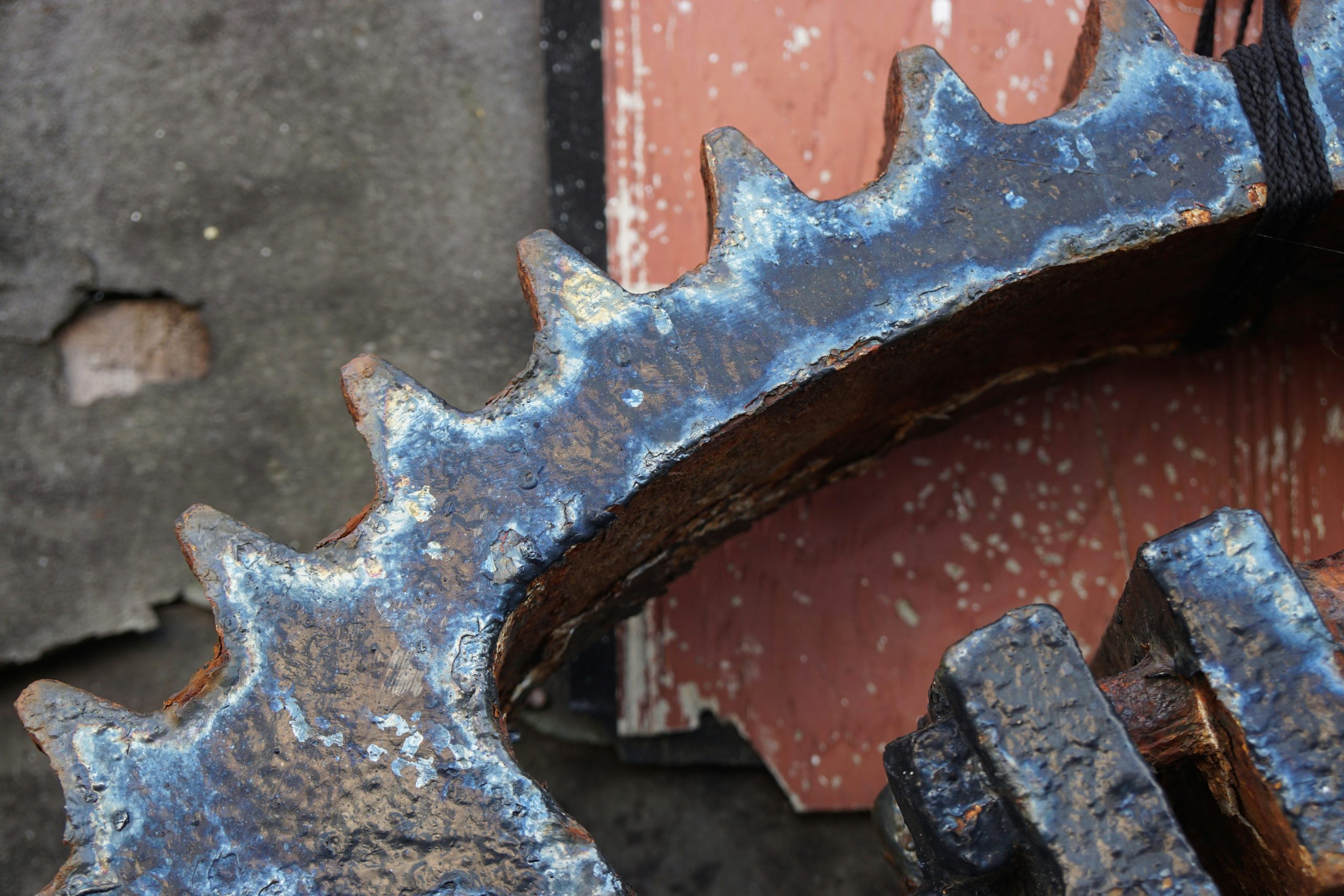
Let’s get straight to it: understanding gear tooth failure patterns is crucial for keeping your machinery running smoothly, preventing costly downtime, and ensuring safety. It’s not just about a gear “breaking”; it’s about how it breaks, which tells you why it broke. This knowledge is your best friend when it comes to maintenance, troubleshooting, and even design improvements. Instead of just replacing a gear, you can address the root cause and prevent the issue from happening again.
Before we dive into the specific ways gear teeth fail, it’s important to grasp the common culprits behind these failures. Often, a combination of these factors is at play.
Overload & Misalignment: The Dynamic Duo of Destruction
When gears are subjected to forces beyond their design limits, or when they aren’t meshing correctly, you’re asking for trouble.
Excessive Torque
This is pretty straightforward. If you push a gear harder than it’s designed to be pushed, it will eventually give out. This can happen due to unexpected surges in power, a sudden increase in the load being driven, or even just continuous operation at the upper end of its specified capacity. Think of trying to tow a much heavier load than your vehicle is rated for – something’s going to snap.
Shock Loads
Unlike a steady overload, shock loads are abrupt, high-impact forces. Imagine dropping a heavy object onto a gear, or a sudden jam in the driven machinery. These instantaneous forces can cause immediate damage, even if the average load is well within limits.
Manufacturing and Assembly Errors
Gears, especially in complex systems, need to be manufactured and assembled with precision. Small errors can have big consequences.
Incorrect Center Distance
If the distance between the centers of two meshing gears isn’t spot-on, it can lead to tight spots, loose spots, and uneven load distribution across the tooth faces. This puts undue stress on certain areas.
Shaft Deflection
Under load, shafts can bend slightly. If this deflection isn’t accounted for in the design, it can pull gears out of alignment, causing them to mesh improperly.
Bearing Wear or Failure
Bearings are there to support the shafts and gears. If bearings wear out or fail, they can allow the shafts to move out of alignment, directly impacting how the gears mesh.
Lubrication Issues: The Silent Killer
Lack of proper lubrication is a huge problem. It’s like running an engine without oil – things heat up, friction increases, and components wear out fast.
Insufficient Lubricant
Simply not having enough oil or grease can lead to metal-to-metal contact, increased friction, and rapid wear.
Contaminated Lubricant
Dirt, metal particles, water, or even degraded lubricant can turn your protective film into an abrasive paste, grinding away at the gear teeth.
Incorrect Lubricant Type
Not all lubricants are created equal. Using the wrong type (e.g., an oil not designed for high-pressure applications or high temperatures) can lead to premature failure.
Material Defects and Fatigue: The Inherent Weaknesses
Sometimes, the problem lies within the material itself or how it responds over time.
Inclusions and Voids
During manufacturing, tiny imperfections like impurities (inclusions) or air bubbles (voids) can be left within the metal. These act as stress concentrators, making the gear more susceptible to cracks and failure in those spots.
Residual Stresses
The manufacturing process itself (e.g., machining, heat treatment) can leave internal stresses in the material. While some are beneficial (like compressive stresses from shot peening), uncontrolled tensile residual stresses can promote crack initiation.
Endurance Limit Exceedance
Every material has an “endurance limit” – a stress level below which it can theoretically withstand an infinite number of load cycles without failing due to fatigue. If the gear teeth are consistently stressed above this limit, even if it’s below the yield strength, fatigue cracks will eventually form and propagate.
For a deeper understanding of the various applications of industrial gearboxes and how they relate to gear tooth failure patterns, you may find the article on industrial gearbox applications insightful. It explores the different environments and conditions under which gearboxes operate, which can significantly influence wear and failure mechanisms. You can read more about it here: Industrial Gearbox Applications.
Breakdown of Common Gear Tooth Failure Patterns
Once you understand the why, let’s look at the what. These are the visual clues that tell you what’s going on.
Wear: The Grinding Away of Material
Wear is the gradual removal of material from the tooth surface due to friction and contact stress. It’s often a precursor to more severe failures if not addressed.
Abrasive Wear
This is like sandpaper on your gear teeth. It occurs when hard particles (dirt, manufacturing debris, wear particles from other components) get trapped in the lubricant and act as an abrasive, grinding and scratching the tooth surfaces. You’ll see fine scratches, grooves, and a general dulling of the surface finish.
Corrosive Wear
When gears operate in corrosive environments or with contaminated lubricant (especially water ingress), chemical reactions can attack the metal surface. This leads to a roughened or pitted surface, often with discolored areas. It weakens the tooth surface, making it more susceptible to other forms of wear and fatigue.
Polishing / Mild Wear
Sometimes called “run-in wear,” this is usually an expected, non-damaging form of wear that occurs during the initial operation of gears. The high points on the tooth surfaces are gently worn away, leading to a smoother, often shinier surface as the gears conform to each other. If it continues excessively, it can thin the teeth too much.
Moderate Wear
This is a step beyond mild wear. The tooth profile begins to change noticeably, often becoming thinner at the tip or root. You’ll see smooth, worn areas that lose their original machining marks. It indicates that the operating conditions are too harsh, or lubrication is becoming inadequate.
Excessive Wear
At this stage, the tooth profile is significantly altered, leading to backlashes, noise, and reduced load-carrying capacity. The teeth appear thin, sharp, or even knife-edged. This is often an irreversible condition requiring gear replacement.
Surface Fatigue: Cracks and Pits from Repeated Stress
Surface fatigue is a common failure mode where repeated loading causes microscopic cracks to initiate and propagate just below the surface of the gear tooth.
Pitting
This is perhaps the most common form of surface fatigue. It starts with sub-surface cracks that grow, eventually detaching small pieces of material from the tooth surface, leaving small, irregular craters or “pits.”
Initial Pitting
Small, shallow pits that are often hard to see without magnification. This can be normal during the initial “run-in” phase as the gear surfaces conform. However, if it progresses, it’s a problem.
Progressive Pitting
As the name suggests, this is when pitting continues to worsen, with pits growing in size and number, often congregating in loaded areas of the tooth (pitch line region). This indicates that the contact stresses are too high, or lubrication is insufficient.
Spalling
This is a severe form of pitting where large flakes of material detach from the tooth surface, leaving large, deep craters. This is a critical failure that significantly reduces load-carrying capacity and can lead to tooth breakage.
Scuffing / Scoring / Galling
This is a nasty one. It occurs when the lubricant film breaks down, leading to direct metal-to-metal contact between meshing teeth. The high spots on the tooth surfaces weld together momentarily and then tear apart, causing gross transfer of material from one surface to the other. You’ll see rough, torn, and often discolored areas along the direction of sliding. It’s usually accompanied by high temperatures.
Tooth Breakage: The Catastrophic Failure
This is the most obvious and often immediate failure, where a portion or the entire tooth separates from the gear.
Fatigue Breakage
This is the most common type of tooth breakage. It starts with a tiny crack, usually at a point of high stress, such as the tooth root (where bending stresses are highest) or an inclusion within the material. This crack then grows over many load cycles until the remaining material can no longer support the load, and the tooth fractures.
Root Fillet Fracture
These cracks typically originate in the root fillet (the curved area at the base of the tooth) due to repeated bending stresses. The fracture surface usually shows characteristic fatigue beach marks, indicating cyclic crack growth, followed by a final fracture zone.
Tip Fracture
Less common than root fillet fractures, tip fractures occur when cracks initiate at the tooth tip, often due to high contact stresses, stress concentrations from impact, or a manufacturing defect at the tip.
Overload Breakage
This is an instantaneous failure that happens when a sudden, excessive load exceeds the ultimate strength of the gear material. There’s little to no evidence of prior fatigue crack growth. The fracture surface will typically look rough, coarse, and jagged, consistent with a ductile or brittle fracture, depending on the material and temperature. Think of bending a paperclip back and forth many times (fatigue) versus just snapping it with one strong pull (overload).
Impact Breakage
Similar to overload breakage, but specifically caused by a sudden, sharp blow or impact. This can happen if a foreign object gets caught between teeth, or due to severe shock loads. The fracture surface will show characteristics of brittle fracture, often with very little deformation around the break.
Beyond the Obvious: Less Common but Important Failures
While the previous categories cover most gear failures, these are also worth noting.
Understanding gear tooth failure patterns is crucial for maintaining the efficiency and longevity of industrial machinery. For those interested in a deeper dive into the topic, a related article on industrial gearbox repair provides valuable insights into common issues and solutions. You can read more about it in this informative piece on industrial gearbox repair in Cincinnati, which highlights the importance of timely maintenance and expert intervention to prevent costly breakdowns.
Plastic Flow / Cold Flow
This occurs when the contact stresses are so high that the material flows or deforms under pressure, rather than fracturing. You’ll see a permanent deformation of the tooth profile, often a “dishing out” or “spreading” of material at the contact surfaces. It’s more common in softer materials or under extremely heavy loads, especially if accompanied by high temperatures.
Thermal Cracking / Heat Checking
This is usually a secondary failure, caused by localized overheating of the tooth surface. Rapid heating and cooling cycles create thermal stresses that can lead to a network of fine cracks, often resembling a spiderweb pattern on the tooth surface. This can significantly weaken the tooth and lead to further failure. It’s often seen in heavily loaded gears with inadequate cooling or lubrication.
Sure, here is the sentence with the clickable link:
Please feel free to contact Industrial Gearbox Solutions for any inquiries.
The Takeaway: It’s All a Puzzle
Understanding these failure patterns isn’t just academic; it’s a practical skill that can save you significant time and money. When a gear fails, don’t just replace it and move on. Take the time to examine the broken parts. Look at the wear patterns, the fracture surfaces, and the location of the damage. Each clue tells a story about what went wrong.
By properly identifying the failure pattern, you can then investigate the root cause: was it an alignment issue, poor lubrication, an overload, or a material defect? Addressing that root cause will ensure your equipment runs more reliably, for longer, and with fewer unexpected breakdowns. It’s about being proactive, not just reactive.
FAQs
What are the common gear tooth failure patterns?
The common gear tooth failure patterns include pitting, wear, scoring, scuffing, and cracking. These patterns can occur due to various factors such as improper lubrication, overloading, misalignment, and material defects.
What causes pitting in gear teeth?
Pitting in gear teeth is typically caused by surface fatigue due to repeated contact stress. This can be exacerbated by inadequate lubrication, contamination, or improper gear meshing.
How does wear occur in gear teeth?
Wear in gear teeth can occur due to abrasive particles in the lubricant, inadequate lubrication, or excessive sliding motion between the gear teeth. This can lead to a gradual loss of material from the tooth surface.
What is the significance of scoring in gear teeth?
Scoring in gear teeth can indicate localized overheating and metal-to-metal contact. This can be caused by factors such as misalignment, excessive load, or inadequate lubrication, and can lead to accelerated wear and potential tooth failure.
What are the common causes of gear tooth cracking?
Gear tooth cracking can be caused by factors such as overloading, material defects, improper heat treatment, and stress concentrations. Cracks can propagate due to cyclic loading and lead to catastrophic gear failure if not addressed.